Game Cube Portable 5.6" LCD Screen Mod
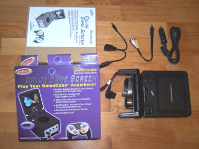
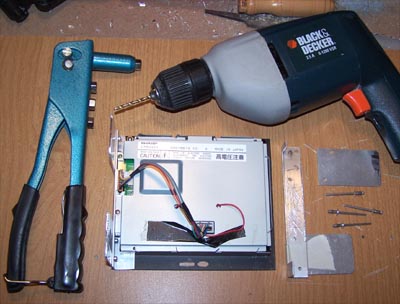
Last Spring I bought a Game Cube portable game screen from AllElectronics.com but didn't have time to mod it, at USD$54 it was a good deal and they sold out on them quick. The same screen can be had online with a little searching for $50-$95, below shows everything included.
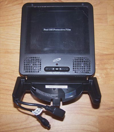
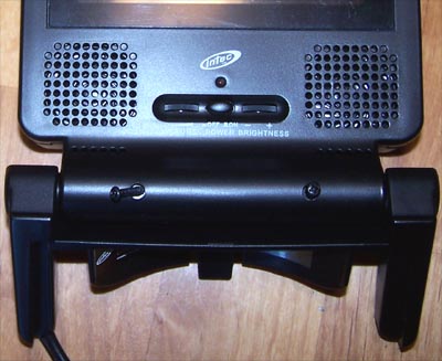
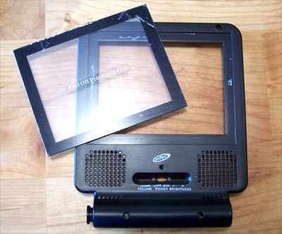
Here is a close up of the modding victim still all in one piece, on the face of the screen there is an on/off switch, power LED and dials for volume and brightness. There are speakers included as well, color those gone. The cables coming out of the left foot are for 12V DC and the other is the AV connector for the Game Cube.
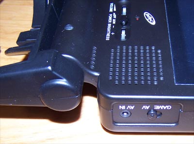
On the right hand side of the screen is the AV in and selector switch that toggle between the game and AV inputs.
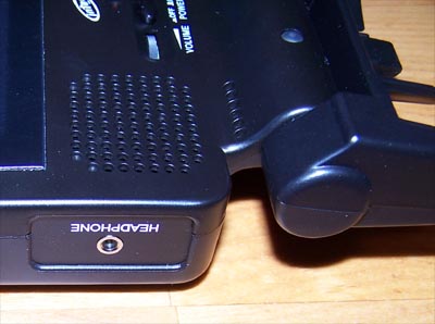
On the left hand side of the screen is a headphone jack, which will not be used in this mod.
Time to break this thing open and see what makes it tick, first off there are rubber stoppers over the screws at the bottom of the screen that need to be removed, then remove the screws (as shown below) and flip it over.
![]()
![]()
There are two screws on each leg that need to be removed...
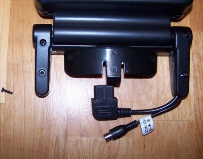
And two more screws to take out inside one leg, the whole bottom section can now be removed.
To separate the two halves of the plastic housing grab the plastic where it's split at the bottom of the screen and yank it apart, don't be afraid to be forceful because there is no graceful way, it's the only way it comes apart. Below shows where we're at...
The screen itself is just double side taped onto the front of the housing and comes up pretty easily.
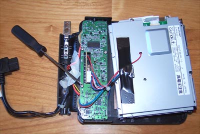
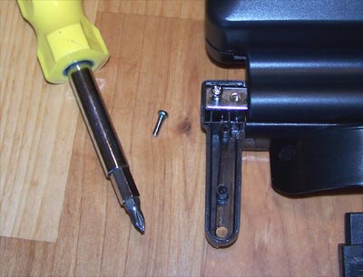
The screwdriver below is pointing to one of three screws that hold the PCB onto the housing, remove them all.
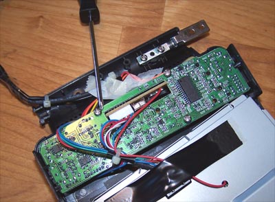
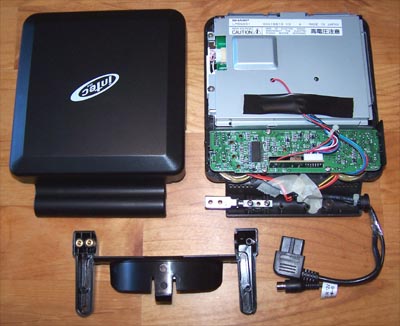
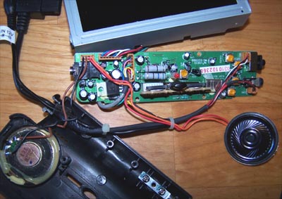
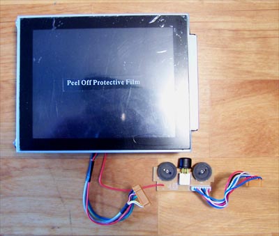
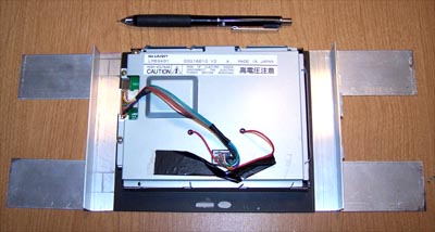
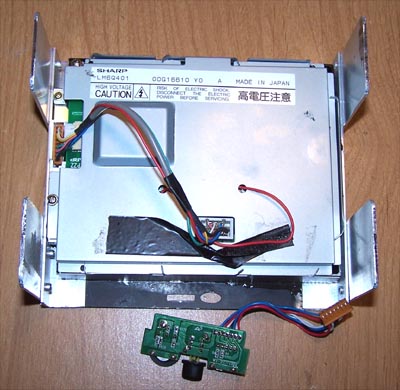
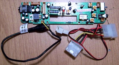
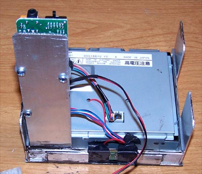
Here it is taken apart, I unplugged nearly everything from the PCB to make things easier to work with, the crappy little speakers will not be used in this mod.
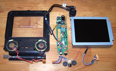
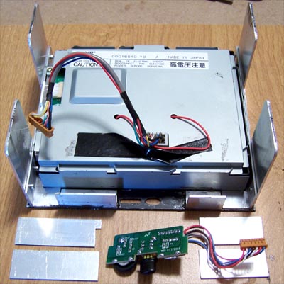
Below shows the Game Cube screen broke down into workable bite sized pieces and now that I can see what's involved it's time to formulate a plan. I did a little research and found the pin-out for the Game Cube cable, I don't plan to do it but the cable could be hacked into S-video fairly easily. Doing it would allow you to hook another device to the screen externally and be able to flip between them using the AV switch, but like the speakers it isn't necessary for this mod since I plan to lock the AV input switch in the on position and get the signal via the RCA video input.
"All things lively must be used" - Adam Ant. Pop out the plastic screen cover, it is just double stick taped on so start at a corner and peel it up.
Carefully center the plastic piece over the screen and press it down, the tape residue on the front of the screen combined with what's on the plastic is enough to hold it in place so it can protect the bare LCD screen underneath.
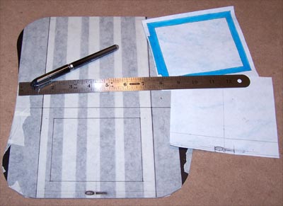
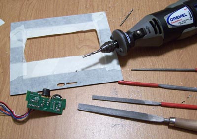
I drew up a couple paper templates for the face of the screen and taped it down so I can figure out the positioning.
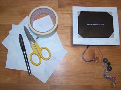
As for what material to use for the face of the mod I chose a Steelpad4S aluminum mouse pad that I no longer use, there is enough material to give me two tries at cutting it right.
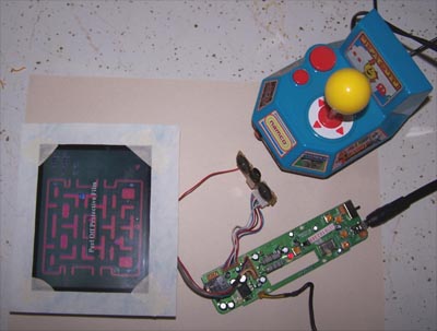
No sense in destroying a perfectly good mouse pad if the screen doesn't work so I wired it up and then fired it up... the picture below shows that it works beautifully.
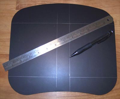
Steelpad4S, you served me well as a mouse pad but the time has finally come for you to suck Dremel and die... I mean that in a good way. Next step is to mask the mouse pad off, measure it up and mark down lines for cutting.
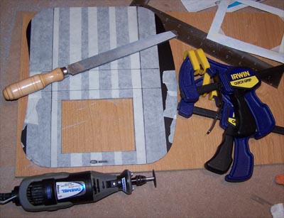
I cut the inside edges that sit next to the screen first, it's easier to do while the piece is whole rather than cutting the outside edges first and then fumbling with it, besides it allows you to keep your fingers further away from the rotary tool which is always good. I also filed off the inside edges up to the marked lines, then cut the outside lines and filed those edges as well.
![]()
![]()
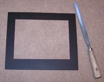
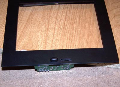
I still have a little fine tuning to do with a file but it's looking good so far (see picture below) and I could almost leave it as is... almost. I'm going to cut the power and brightness controls into the bottom of the faceplate, it isn't in any way necessary for this mod to work, the controls could just as well be hidden behind it all. When the power button is left in the on position the screen will only power up when a signal is present anyway, but the front mounted controls (however unnecessary) will look cool.
I masked the face plate off again, front and back, then measured and marked the location of the power button and brightness dial onto it. I carefully drilled out as much material as I could with the Dremel and then started filing away, testing for fit as I went.
Below shows the final test fit, not too shabby. I used a marker to color in the bare aluminum edges around the button and dial as well as the rest of the face plate edges, paint will be used as a more permanent solution later.
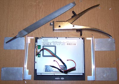
With the face plate made it is time to figure a way to mount the LCD into the PC, for this I used Alum-Angle. I marked the shape of the LCD onto the Alum-Angle in preparation for cutting.
I used a nibbler to cut the side pieces to shape and then filed everything smooth, I also nibbled and file rounded the forward edges of the mounting tabs.
I measured out the best spots to connect the pieces together then drilled holes in the side pieces, traced the pattern onto the mounting tabs and drilled them out, I then rivet the parts together.
Below is a close up of one side of the riveting... it's actually both riveting and exciting.
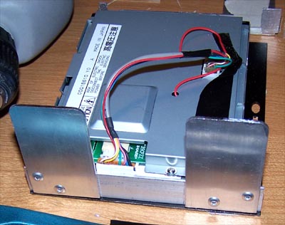
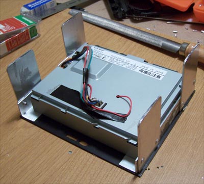
Both of the mounting brackets are finished and shown below in their final test fit, all that is left now is to connect everything together.
I used J-B Kwik to hold the Alum-Angle sides onto the edges of the screen and then roughened up the backside of the faceplate in prep for attaching the LCD.
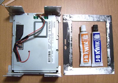
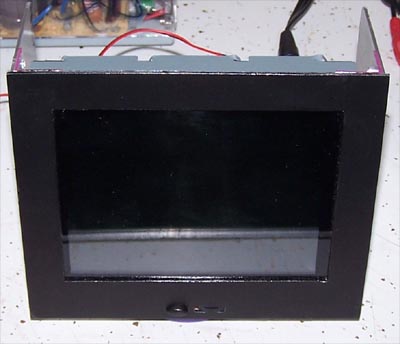
I mixed up some J-B Kwik and applied it around the edges of the faceplate, then carefully positioned the LCD on top of it. Next up is mounting the power button/brightness wheel PCB to the back of the face plate.
I used a piece of corner Alum-angle cut to fit, scuffed up and J-B Kwik'ed to the back of the face plate, the bottom corner edges of the PCB will sit on top of the Alum-angle. I cut two pieces of flat Alum-angle to fit the shape of the outside edges of the PCB and two more pieces to hold it all in place.
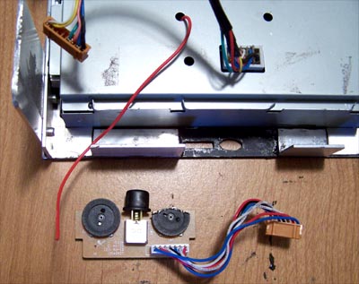
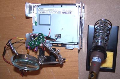
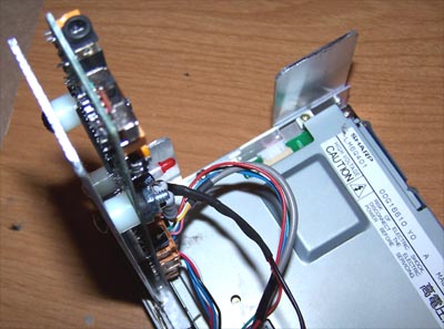
Before I can mount the controls I first have to fix them, early on in the mod the wire that goes from the back of the LCD to the PCB for the brightness wheel had broken off.
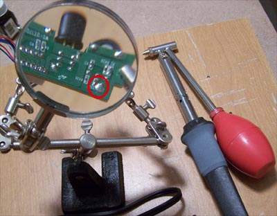
No big deal, the glob of solder circled in red needs to be removed before I can reattach the wiring... the $11 de-soldering iron shown below made short work of it
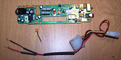
I decided that before I broke out the soldering iron it would be a good idea to wire up the power connector to the controller board and solder everything at once. Below shows the power connector cable on the left and a molex pass through power cable on the right.
The following picture shows both cables cut, the wires stripped back and heat shrink tubing slid onto the power cable wires.
I used a helping hands magnifier to hold the power wire and control PCB in preparation for soldering, two minutes later it was done.
![]()
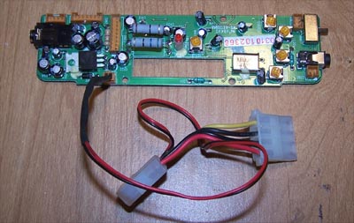
I fit the heat shrink tubing over the soldered wiring and used a lighter to heat it up, below shows the new power cable plugged into the controller board.
I cut a piece of flat Alum-angle to mount the controller board onto, I marked and drilled mounting holes, scuffed up the bottom edge and then J-B Kwik'ed it into place.
I used nylon spacers to hold the board away from the aluminum and a screw with a rubber grommet between the nut and PCB.
Since I do not currently have a PC with three open bays to fit this mod into I will wait to mark and drill the case mounting holes on the side brackets of the LCD.
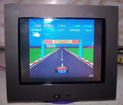
Which also means that the best in action shots I can provide at the moment are pumped out of a Namco hand held video game while sitting on a counter, it does however show that the mod will work in a PC via RCA composite video.
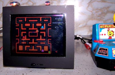
The degree of viewing angle for the LCD is kind of weak meaning you have to be almost right in front of it for it to show correctly, but the colors are bright and the image is fairly crisp.
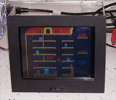
Mappy, I never really liked that game... I measured the heat out put of the LCD using an infrared thermometer, heat was minimal around the screen though there is a hot spot on the controller board that measured 105ºF.
If I had more time I would have hacked the GameCube AV cable into S-video and flipped the controller board over so that the input for composite video and the AV switch were accessible on the face plate... if I find time later I still might.
On my screen I used the original plastic that covered the screen but now wish that I hadn't as it scratches far too easily, better to not cover the screen with anything. Another thing that bugs me is that the mod takes up three 5.25" bays, if I do end up putting this LCD mod into a system I will make some brackets to mount a couple hard drives behind the screen... wasted space is just that.
Happy Modding