search here

You can visit our sponsor's for help

PC Troubleshooting Plus

Start with a basic PC set up to eliminate the suspects and find a faulty component

You've just built your PC you're ready to go. You hopefully hit the power button and await the boot up 'bleep' followed by a pleasing flow of text appearing on your monitor - but wait... no bleep, no display, no sounds or lights - what's going on?

Judging by our messaging forums, this is a common horror for our budding PC builders. Having answered many questions on the subject, we've put together this 'advanced troubleshooter' to help you through these difficult times.

With so many complex parts and connections the possibilities of locating the fault seem endless. The reality is that by a simple process of elimination it should be relatively simple (if perhaps a little time consuming) to track down that 'spanner in the works'.

First of all, it is necessary to understand what is happening during the 'boot' process and the minimum hardware needed to achieve a successful boot of the system.

  1. The Power button is pressed.
  2. The Motherboard checks that the CPU is able to process information correctly.
  3. Built in software called the BIOS is processed by the CPU.
  4. The CPU, RAM and Video Card are all checked for basic functionality.
  5. The system will give one 'bleep' to indicate that the system passed all the initial tests, or a series of bleeps to indicate a specific fault.
  6. The next part of the BIOS is run and a display is sent to the monitor.
  7. The BIOS will then do several further tests on connected hardware (RAM, Keyboard, Mouse etc.) and display any errors
  8. The system will then attempt to load the Operating System software from the designated boot drive.

From the above procedure we can determine that a 'bootable' system will only need a PSU, Motherboard, CPU, RAM and a Video card. This will be the start point for tracking down the fault...

Back to basics

Assuming that your new PC is completely assembled, you'll need to undo some of your previous work. First off, power the system off and disconnect all the external cables, including the mains cable.

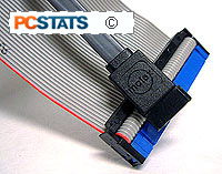
Inside the case, disconnect any IDE and FDD data cables from the motherboard and disconnect all the front panel connectors except the Power switch cable (it is a good idea at this point to double check with the manual that the Power switch cable is connected correctly.)

Also, remove any or all of the Adapter cards (e.g. modems, soundcards etc.) except for the Video card.

First test boot

Connect just the base unit mains cable and the monitor cable. The rest can be left unconnected for the moment. If there is a switch on the PSU next to where the mains cable plugs in, make sure it is switched to ON.

Press the Power button on the front panel. If your system boots and displays text on the screen, skip to the Bootup is OK, what now? section of this article.

If your system is still not booting at this point, you've eliminated a good deal of possible problems and have only a few parts to test for the fault. We've established that the fault lies either in the PSU, Motherboard, CPU, RAM or Video Card.

Take each part in turn (leaving the motherboard till last) and either replace it with a 'known good' item (i.e. from a working PC) or test it in another working PC. The faulty item can then be easily identified as the one which:

1. When replaced with a 'known good' one allows the PC to boot
or
2. Causes a good PC to stop working correctly.

If you get as far as testing the Motherboard, it is the item with the problem. Before you take it back for a replacement, there are a couple of things you can do to make sure it is faulty.

1. Double check that your CPU and Memory are compatible with your motherboard and that you have configured the motherboard correctly as per the manual.

2. Locate and follow the procedure in the manual to reset the BIOS.

If you've done all this and still no joy, re-package the motherboard and take/send it back to the retailer for testing/replacement.

Bootup is OK, what now?

If your system booted successfully in the 'Back to basics' section, you will have tested the fundamental parts of your PC. The fault therefore must lay in one the devices presently unconnected in your system.

Fault diagnosis at this stage is easier, but can take longer. Your aim now is to connect one item or connector at a time, then power up the system, then connect another item or connector, power up etc. until the system fails to boot again. One of two things will happen:

1. Once all the items are reconnected the system continues to work correctly (Problem solved!)

or

2. One of the connections/items will cause the system to fail at the next boot.

If you get to stage 2, the last item you connected has the fault. Confirm that you have connected it correctly, with it's instructions (if any) and return it to the retailer if the problem persists.

The Art of Overclocking; Is It For You?

The Art of Overclocking; Is It For You?

I recently went to one of the local computer stores here in Toronto to chat with my friend Marlon about my new Peltier thermoelectric cooler setup. One of his customers who was standing near by listening in interrupted to ask "is it really worth all the trouble for the last few MHz"? As an enthusiast I take pride in squeezing as much performance as I can from any given computer part (CPU, videocard, memory, etc) so I obviously said "Yes!"

Skeptical, he went on to ask me a couple more questions. For instance; "I'm an average PC user, how would I benefit from overclocking?" and "just how much performance difference do you notice?" We talked for a bit and in the end, we came to a conclusion that overclocking was actually not necessary for him because of the type of computing he did.

Since a lot of readers take the time to e-mail their questions in on this topic, I figured it's about time for me to write a little on the subject, and hopefully explain the benefits of overclocking. Overclocking isn't necessary for everyone, but hopefuly by the end of this you'll know whether it is right for you!

Who overclocks, and why do they do it?

Gamers out there know full well that while a system may run games just fine, it can never really be fast enough or pump out enough frame rates every second. As a gamer myself, I need extremely high frame rates to play any FPS competitively online. I would like to get well past 150 fps in every game from UT2003 to Quake III (yes I still play it now and then), or even Raven Shield. I know what most will ask, "Why the heck would you need that many frames per second?"

The reason behind this is because when my frame rates start to tank - say someone throws a few frag grenades, or there are a few explosions at the same time - I don't want my frames per second to drop below a certain point.

If your gaming rig is getting a bit old and you'd like to get a bit more performance out of it without having to invest a lot of money, overclocking may be able to hold you over till the next major upgrade. If you're a 3DMark freak (it's ok, I am one too) and must have the absolute highest score among your circle of friends, then overclocking is definitely necessary. That should be pretty evident from the three PCstats.com 3DMark2001SE tweaking guides.

However, if you mainly use office based applications or work with 2D programs you probably won't get much of a noticeable 'performance' boost with overclocking. Typically, computers running these types of applications are what we call "user limited" - meaning the slowest link in the whole computer system is the person who is actually using it.

Dangers/Drawbacks of overclocking

First and foremost, overclocking will generate more heat and heat is the #1 enemy of electrical devices like processors. If you cannot remove the additional heat, the life expectancy of your components and stability of a system will certainly decrease. Usually this means the overclocker will have to invest a bit of money for a larger or better heatsink/fan for the processor. Sometimes, it also means better cooling for some of the other components like the videocard, memory and MOSFET's on the motherboard itself.

Most overclockers out there would scoff at the notion that their overclocked systems is unstable. An inexperienced/novice overclocker though may run into stability problems at the beginning because they're not familiar with how to setup a functioning overclocked system. Once they learn the in's and out's, it's not very difficult to run an overclocked system 24/7 without sacrificing stability. I for one would never sacrifice speed for stability, as my data is more important to me then the additional speed.

How much does all this cost?

Yes it does cost money to overclock like the pros, and depending on how much you want to push your system it can cost a great deal or actually very little. If you're really hardcore, buying a retail phase change cooler can cost well over $1000+ CDN. If watercooling sounds like a better answer that type of cooling can cost in the range of $300-500 CDN. Most overclockers out there use conventional HSF's, and luckily a mid to high end air cooler will only cost $50-90 CDN. To get a feel for what heatsinks you should be looking at, head on over to www.frostytech.com - they have over 200 heatsinks reviews online.

Assebling a pc on your own

  • WHERE TO BEGIN?

  • If you are a beginner at computers, begin at your local small computer store. For the purposes of buying parts you are much better off dealing with a small store than a large chain or electronic warehouse, provided you get a good feeling about the place when you walk in of course.

    Small stores are used to dealing with computers in terms of individual components, so they are better equipped to help you out. Tell them you are planning to build your own PC. They will be able to make sure that the parts you get are compatible, at least. You will have an idea of what you want the computer to do once it's built, so go with that. Once you have all the parts on the list, it's time to start building your computer.


    First though, a brief rant about static electricity. This is where things may get a little argumentative. First things first, there is no doubt that Electro-static discharge can destroy computer components. Static Electricity is also known as ESD, or that shock you get when you touch the doorknob after walking across the office carpeting.

    The question is, how careful do you have to be? Is it necessary to properly ground yourself with an electrostatic wrist strap before touching computer components, or do you just exercise a few simple precautions?

    I have to admit I fall on the latter side, but I'm not the only one. Walk into any of those small computer stores you see by the hundred in any city, and go to the back. I'll bet you the guy up to his elbows in computer parts there is not wearing a wrist-strap, most likely because he is also the guy who is going to come out to the front and try to sell you something too. Yet this store will turn out computers as reliable on average as any other computer store you could walk into.

    Sure you could say "what about the big manufacturers? What about Dell? Don't their techs wear wrist straps?" I'm sure they do. The thing is, I don't believe that Dell (as one example) has a parts failure rate that is significantly lower than that of any other major or minor manufacturer, and if there is a minor difference, it is going to be because major manufacturers have a standardized quality control system in place that your local AlphaBetaGamma computer store is not going to be able to emulate. With a few simple precautions, I don't think we need to worry much about ESD.

  • Simple precautions: Build your computer on a hard surface, away from carpets if possible. Wear shoes and a short-sleeved cotton shirt. Synthetic materials like polar fleece are excellent static generators, so it's best to wear natural fibers which don't create little lightning clouds everytime you shift your feet.

  • Use the anti-static bags that come with most computer components as mats to rest the components on your workspace. If you often get static shocks in your home, it may be a good idea to plug the power cord into your powersupply and turn the switch at the back to the OFF position. You can then touch the metal case of the power supply (or the unpainted metal area of the computer case if the PSU is already mounted) to ground yourself while you work.

    Be sure to unplug the power cord from the power supply before connecting any of the power cables to the components, however.

  • Handling Components Correctly
  • When handling computer components like motherboards, videcards, memory, or even a hard drive it is best to hold them by the edges. If you hold that videocard (for example) by the edges the PCB it is less likely that your fingers will even come in contact with any conductors, decreasing the chance of causing any ESD damage further still.

    This is not only a good precaution, it is also a good habit as any Electrical Engineer will tell you. Certain electrical components (namely capacitors) can store an electrical charge even after the power has been disconnected for sometime that can deliver a nasty shock, or kill if they are sufficiently powerful enough... Don't worry though, all the components we'll be installing in the computer are more afraid of you, and don't carry enough charge to cause you harm.

    Still, grabbing a board of electronics like you would a sandwich puts your fingers in direct contact with the little metal leads from soldered-on electrical components. If for example, your finger came in contact with the leads from a powerful enough charged capacitor you could get a very strong shock. The opposite rings true if you happen to grab a videocard when you're all charged up with static electricity. Instead of receiving a nasty arm-zapping shock, you may just deliver a nasty bolt of static electricity to a sensitive microchip - damaging it in the process.

    Obvious precautions: Try not to remove articles of clothing while you work on the computer, for esthetic as well as practical reasons. DO NOT let your cat near the computer parts. Cats are walking static death bombs.

    Now that the ESD precautions are out of the way, what do you need to build your computer?

  • - ATX computer case with at least 350-watt power supply

  • - Intel or AMD processor with appropriate heatsink

  • - Computer motherboard compatible with your processor

  • - 1 or more sticks of RAM (memory) compatible with the motherboard and processor

  • - 1 or more SATA/IDE hard disk drives

  • - 1 or more optical (CD) drives

  • - 1 floppy disk drive

  • - 1 PS/2 or USB keyboard.

  • - 1 PS/2 or USB mouse

  • - at least one video card (ie. PCI Express, 8XAGP, integrated video, etc.) compatible with the motherboard (this may be integrated into the motherboard on some models)

  • - DVI or VGA monitor (computer screen)

  • - Sound card (these are generally integrated into the motherboard, though depending on your requirements, this may not be enough)

  • - 10/100 Ethernet Network Adaptor aka NIC (if you plan to connect the computer to other computers in your household)

  • - A Phillips-head screwdriver with a long neck, preferably magnetized, because you WILL lose a screw or two during the course of this.

  • - A flashlight is always a good thing to have. So is a big desk, or table where scratches on the surface aren't a big deal.

    Remember, you can also peek at the PCSTATS ShoppingList if you need some current suggestions to this basic list of components.

    The system I am going to assemble in the article is a fairly typical Intel processor based midrange system for office use. Nothing too cheap, but nothing too expensive either.

  • BUILDING THE COMPUTER ,FIRST STEP

Step 1: Preparing the case.

Remove the empty computer case from its packaging. Unscrew and remove both side panels, and take out any items that may be inside. Lay the case down flat on your workspace, so that the mounting space for the motherboard is facing up (see pic 1).

PCSTATS

Step 2: Installing motherboard risers.

You need to determine if the case has the appropriate risers installed. Risers, or spacers, keep the motherboard from touching the metal surfaces of the case after it is installed, avoiding a short-circuit and a wrecked computer.

Risers are your friends. Any new case will include some form of riser, metal or plastic. See the picture below for typical examples. They may or may not be pre-installed into the case.

PCSTATS

Remove your motherboard from its packaging and lower it into the case.


INSTALLING THE MOTHERBOARD CPU

Line up the ports on the motherboard (PS/2, USB, etc.) with the appropriate holes in the back panel I/O shield of the case (see pic below).

PCSTATS

Once the board is temporarily in place, observe which screw holes in the case line up with the holes in the motherboard. These are where you will need to place risers if they are not already pre-installed. Remove the motherboard and insert the risers in the appropriate screw holes.

Step 3: Installing the CPU

Place your motherboard flat on top of the anti-static bag it came in. Ensure that the lever on the cpu-socket is upright (open). Holding the CPU gently on the sides with thumb and fingers, lower it into the socket, ensuring that the arrow on the CPU matches the arrow indented into the socket (see pic below). The processor is keyed to fit into the socket a certain way, and only that way.

PCSTATS

Very little effort should be required to insert the CPU in the socket. If you cannot get the CPU to sit evenly DO NOT force it. Remove it completely and try again. Ensure that the CPU is sitting flush with the socket on all sides. No pins should be visible. Once you are sure the CPU is correctly seated in the socket, lower the lever until it locks. This will require a small amount of force.

Note: These instructions will work for any recent CPU/motherboard combination except for Intel LGA 775 motherboards and processors. Since the pins are built into the socket not the processor, the installation process is slightly different for these devices. To install an LGA 775 compatible Intel chip, you first unlatch the lever at the side of the socket.

This allows you to open the protective cover over the actual socket and the delicate pins it contains. Be very careful that you do not touch the actual pins within the socket, as they are extremely fragile. With the cover open, you can lower the processor into the socket just as you would any other type of chip. Notches in the socket and an arrow on both the processor and the bottom left corner of the socket help you line the processor up correctly. Once the chip is seated properly in the socket, you can close the protective cover and re-latch the lever.

Otherwise, the orientation of the CPU may be different, but the method of inserting it is the same for older socket chips; whether they be Intel, AMD or VIA processors. This guide does not cover slot-based processors, as they are no longer used.

Step 4: Installing the heat sink and cooling fan (socket 478)

Cute little guy, ain't it? German Engineering, so I'm told... Make sure the 2 levers on the top of the heat sink are in their default unlocked position. Since Intel processors come with a heatsink, installation is pretty straight forward. Even things like thermal interface materials (pastes, pads, or goo's) are already pre-applied for you.

PCSTATS

Lower the heat sink gently into the plastic frame around the processor so that the heatsink metal sits evenly on all sides. Push down on the plastic top of the heatsink until the hooks on each side lock into the heatsink retention mechanism frame on the motherboard. This will require some force. Holding one side of the heat sink securely, pull the lever on the other side over until it locks. Again, this will require some force.

PCSTATSRepeat the procedure for the other lever. Consult your motherboard manual for the locations of the three-pin fan headers. There should be one close to the CPU socket. Plug the fan power cord into that header.

Don't choose a fan header at random, make sure the heatsinks' fan is being powered by the correct header for this purpose. If you get the wrong one, the is a chance the fan may shut off when the computer is in suspended mode - meaning the processor will overheat.

There are many different types of after-market heatsinks for both the Intel Pentium 4 and AMD Athlon processors. We're only covering the installation of the stock Intel heatsink, but the basic principle for installing after-market coolers is the same. Some heatsinks may come with a small package of white silicon-based thermal compound which needs to be applied before the heatsink is installed. If this is the case, only use a very small amount, and spread it over the processor's core only. The thermal compound is only used as an interface between the bottom of the heatsink, and the portion of the processor which it comes in contact with.

Some thermal compounds are made with conductive metals to achieve better thermal conductivity between the heatsink and processor. If you decide to try these types of Thermal Interface Materials (TIM) out, be sure you clean the surface of the processor and base of the heatsink with a soft cloth and Methyl alcohol gently before applying a small amount of the material. Silver-based TIMs are conductive, so do not get them on any electrical components!

Installing LGA 775 (socket 775) heatsinks

Intel’s new heatsink design for the LGA 775 socket is actually less cumbersome and easier to install than the previous designs. In place of the somewhat complex locking mechanism is a simple set of four holes which correspond to four pillar-like fasteners mounted around the body of the heatsink.

Simply lower the heatsink down onto the processor and line each of the fasteners up with the corresponding hole in the motherboard. A hard press on the top of each fastener, four satisfying clicks, and the heatsink is mounted. Attach the 4-pin power cable to the CPU fan header and you are ready to go.

Installing a ‘socket A’ AMD heatsink, or a socket 362/ ocket 7 processor heatsink

The above listed socket types all use essentially the same heatsink fastening mechanism, differing only in the relative fragility of the processors involved. A word to the wise… AMD Athlon, Duron and Athlon XP chips are quite fragile and easily damaged by clumsy heatsink installation. Do yourself a favour and be careful. Any computer shop is going to spot a processor that has been mangled by a careless install and will refuse you warranty service.

These instructions cover the AMD Athlon, Duron and Athlon XP+ Socket A processors, as well as socket-based Intel Pentium 3 processors and older Socket 7 chips by many manufacturers.

The socket has 2 main retention clips, one on each end. Note the raised area at the ‘top’ of the socket, with the socket number written on it. This corresponds to a hollowed-out area on the surface of the heatsink, allowing you to correctly align the heatsink on the socket. If your heatsink does not have this area, the long side of the clip attached to the heatsink should face the raised area. Remember that the heatsink should sit flat and parallel with the surface of the processor when installed correctly.

With the heatsink sitting flat on the processor, hook the short side of the clip to the retention clip on the ‘bottom’ of the socket (the side without the raised area). It should go on easily, as there is no tension on the clip yet. Make sure not to apply any pressure to the heatsink during this operation. Once the clip is attached at one end, push the other end of the clip down gently and examine the way the heatsink sits on the processor. It should be almost exactly parallel and not overlapping the socket. If all looks well, gently but firmly press down on the other end of the clip, so that it attaches to the other retention mechanism. Depending on the heatsink, you may have to use a flathead screwdriver to apply the necessary force to attach the clip. Just be careful not to slip… Once the other retention mechanism is attached, you’re ready to go. Just remember to attach the power cable for the fan!

Installing an Athlon 64/FX heatsink

AMD’s new 64-bit chips have had quite a varied array of sockets so far in their young life. Sockets 754, 939, 940 and AM2 to be specific. Thankfully, the actual installation methods have not changed that much between each of the three designs. Athlon 64 heatsinks clip directly to the plastic retention bracket surrounding the socket. They have a lever on one side of the cooler which also attaches to the bracket and provides extra pressure so the heatsink sits firmly on the processor. The heatsinks are symmetrical so they can fit either way into the retention bracket. Fasten both sides of the heatsink to the clips on the bracket, ensuring that the heatsink stays straight and that you do not put excess pressure on it. Once the ends of the heatsink are fastened, push the lever down firmly so that it grabs onto the clip provided for it.

Step 5: Installing RAM

All modern RAM (memory) is keyed so it can only fit into the DIMM slots a certain way. With modern motherboards, it should not matter which slot you use, though if they are numbered in the manual or on the board, it is always a good idea to go with slot one first. Hold the RAM module next to the slot so that the indentation(s) on the green PCB line up with the bumps in the slot. (see pic below).

PCSTATS

Once you are certain of the orientation of your RAM, open the levers on either side of the DIMM slot and push the RAM module straight down into the slot until both levers snap closed on either side. This will require some force. If it does not seem to be going in with a moderate amount of force, remove the module and re-insert it, making sure that it is exactly lined up with the keyed points in the slot.

PCSTATS

Installed properly, the levers on the sides of the DIMM slots will be completely closed and locked into small cutouts on the outer edges of the RAM module.

Step 6: Installing the Motherboard

Ensure that the motherboard mounting area in the case is free of obstructions and that all necessary risers have been installed in the right spots. If there is an extra riser that does not line up with a hole in the motherboard, make sure you remove it. Lower the board into the case as in step 2. Screw the motherboard into the risers. Note that some forms of risers will not require screws to be used. You can figure it out. Once the board has been securely attached, plug in the 24 or 20-pin main ATX power connector (see pic).

PCSTATS

If you are installing an Intel Pentium 4 machine, you will probably be required to connect one or two extra power connectors (see pic).

PCSTATS

Plug the 4-pin 12V auxiliary power, and 6-pin power connectors in also. Note: some motherboards may not require the 6-pin connector at all.

Consult your motherboard manual for the correct locations of the 'front panel' power and reset button wires, the power and hard-drive LED wires and the speaker. Note that the power and hard-drive LED wires are sensitive to polarity, so they will only work one way around. In theory, positive and negative will be indicated on the board and the plugs... In practice, doubtful, so... trial and error. You will not cause any damage if you get it wrong, though, the LEDs will just not light up.

Step 6: Installing the floppy drive

I have occasionally tried to get away without a floppy disk drive (FDD) on some of my computers, and without exception, I have regretted not having one at some crucial moment.

Ensure that one of the 3.5-inch bays in your case is open. If your case came with rails for the floppy drive, attach them to the sides of the drive and slide the drive into the front of the computer until it clicks into place. Rails are small metal pieces which clip or screw on to the sides of the drive and allow it to be inserted and removed from the case with minimal effort in case you are wondering.

PCSTATS Otherwise, slide the drive into the front of the computer until the faceplate of the floppy drive is flush with the front bezel of the case and the screw holes along the side of the drive line up with the case. When everything lines up, screw the floppy drive in securely on both sides.

Plug in the power cable (see pic to right) carefully, since it is quite possible to miss one of the connectors, which will quite possibly cause some damage when the computer is powered on. Floppy drive power connectors are keyed in most cases, but if not, the red wire should be connected to the pin designated as 1 on the surrounding PCB.

Ensure that the power connector is correctly lined up with all 4 connectors. A flashlight is a good thing to have at this point. The floppy (data) cable is keyed to only fit one way. Note that it is keyed the opposite way to the IDE hard drive and CD drive, so that the red stripe on the cable should be facing the floppy drive power cable.

Floppy drive cables are solid ribbon on one end, and the other has a small section of the ribbon cut and twisted around. Ensure you only attach the floppy cable as shown in the picture below (cut portion of the ribbon attaches to the FDD itself).

PCSTATS

Connect the data cable between the drive and the 'floppy1' connector on the motherboard.

Step 7: Installing the hard-drive

First, we need to ensure that the hard drive is set up to be the master drive on its IDE cable. Each IDE cable can support up to two IDE devices, such as hard-drives, CD-drives, Zip Drives, etc., but in order for this to work, one IDE device must be designated as a master device, and one must be designated as a slave device. You cannot have two master devices or two slave devices on a single cable.

PCSTATS

Examine the top of your hard-drive. There should be a chart there depicting the necessary jumper settings to make the drive a master or slave device. Otherwise, the chart will be somewhere on the body of the drive. The set of jumpers will be on the back end of the drive.

PCSTATS

Ensure that they are set correctly to enable the drive as a master. You may need a set of tweezers to move the jumpers around if you have been biting your fingernails.

Insert the hard drive into the 3.5" drive-tray and screw it in securely on both sides. Note that hard-drives generally use a different sized screw than CD-ROMs and floppy drives for some completely inexplicable reason.

HARD-DRIVES AND CABLES

Attach the Molex power cable to the drive. Unlike the floppy drive power plug, these Molex connectors can only fit into the drive one way, so relax, you can't make a mistake here.

PCSTATS

Attach the Primary IDE cable to the drive (for any recent motherboard, this should be a 80 wire UDMA cable). It will be keyed to only fit in one way, but to make sure, the red or blue on the cable should be facing the hard-drive power cable.

PCSTATS

Attach the long end of the cable to the IDE 0 connector on the motherboard first, then if there are other drives attach those IDE cables to the IDE 1 connector. PCSTATSSerial ATA drives are still fairly new, so we will only cover them briefly.

The Serial ATA cable is keyed to fit into the SATA motherboard header, and hard drive in a certain orientation. It is impossible to attach the Serial ATA cables backwards, and since there is only one hard drive per cable we don't need to worry about the master/slave settings of IDE hard drives.

Serial ATA and IDE are not compatible, so to use SATA hard drives the motherboard must have SATA headers. Some motherboards may come with SATA-to-IDE adaptors, but again the motherboard still must have one SATA header per drive.

The SATA hard drive will require either a 15-pin SATA power connector, or standard 4-pin Molex power connector as we described previously.

Step 8: Installing optical (CD) drive

Ensure that at least one full sized 5.25" bay is open in the case. Examine the jumper settings on the top of the drive, as you did with the hard-drive. Ensure that the drive is set to 'master'. If your case came with rails, screw them to the sides of the CD drive and insert it into the front of the case until it clicks into place.

Otherwise, slide the drive into the front of the computer until the faceplate of the drive is flush with the front bezel of the case and the screw holes along the side of the drive line up with the case. Then, screw it in securely on both sides. Attach the power cable (same as the hard-drive power cable) to the drive. Attach your secondary IDE cable to the drive. Note that generally this should be a regular 40-wire IDE cable, not the 80-wire UDMA IDE cable that is used for the hard-drive. Some DVD drives will use the 80-wire cable, however. See the picture below for a comparison of the two IDE cable types.

PCSTATS

The drive should be keyed, so the cable will only fit one way, but note that the red stripe on the IDE cable should be facing the CD power cable.

PCSTATS

Attach the long end of the cable to the 'IDE1' or 'IDE2' connector on the motherboard.


Getting Sound from a CDROM

In order to get sound out of the CDROM when playing CD's, we need to attach a special cable between the CDROM and motherboard/soundcard. The CDROM should come with this thin 4-pin cable with flat connectors at either end. If not, be sure to pick one up from the store.

PCSTATS

This is the analog audio cable which needs to be connected between the CD drive and your soundcard (or the motherboard if your soundcard is integrated into the board.). This allows Audio CDs to be directly played from your CD-ROM like an audio CD player. Plug the cable from the connector at the back of the CD drive to the 'audio-in' connector on your soundcard or motherboard. The soundcard connector should be fairly obvious, check your manual for the location of the one on your motherboard.

Step 9: Installing the video card

For an AGP videocard: The AGP port is the brown slot at the top of the row of peripheral (PCI) slots that runs down the board. Ensure that the catch (AGP Retention Mechanism) at the far end of the port is open, if it is present.

PCSTATS

Insert the card firmly into the AGP slot. It should settle evenly, with just a tiny fraction of the gold traces at the bottom of the card visible. Screw the card into the expansion bracket.

For a PCI videocard: PCI ports are the white slots running in a row down the rear edge of the board. Which port you choose is fairly irrelevant, though with modern video cards, it is always a good idea to leave the slot below the one you install the card in empty to aid in ventilation of heat. Simply insert the card firmly into the slot. It should sit evenly once inserted, with only a fraction of the gold traces on the bottom of the card visible. Screw the card into the expansion bracket.

Step 10: Installing PCI expansion cards

All PCI cards are physically installed the same way. With modern motherboards, which slots you decide to use should not matter, but it is a good idea to space your expansion cards out in order to help with case ventilation. Simply insert the card firmly into an empty PCI slot. It should sit evenly once inserted, with only a fraction of the gold traces on the bottom of the card visible.

PCSTATS

Screw the card into the expansion bracket.

Step 11: Finishing up

If your motherboard came with any extras, such as Modem or network adaptor riser cards, or additional USB ports on a mounting bracket, now's the time to plug them into the board (consult your manual for the correct locations) and screw them into any free mounting brackets you may have.

Double-check all the wiring. Make sure all connections are firmly attached, and ensure that no wires are running close to the top of the CPU heat sink fan. You do NOT want to jam the CPU heat sink fan, especially with an AMD processor.

Double-check everything again. Now get all those loose screws out.

Step 12: Powering up for the first time

Stand the case upright, if it is not already. Ensure that no wires are touching the CPU heat sink fan. Plug your monitor cable into the video card (VGA) port, and turn on the monitor. Plug your PS/2 (or USB) keyboard cable into the keyboard port. Plug in the power cord and switch the power supply switch to the on (|) position. Press the power button. Suspense.... sparks?

If everything is connected as it should be, all system fans should start spinning, you should hear a single beep, and after about 5-10 seconds, the amber light on the monitor should go green, and you will see the computer start to boot.

Depending on the manufacturer of the Motherboard, you may get a splash screen, or just a memory check. The system will then halt with an error because we have yet to install an operation system. If something has gone horribly wrong, just go straight down to the troubleshooting section. If something is on fire, go to the kitchen. You do have an extinguisher, right?

Now check the front LEDs to see if you plugged them in correctly. Power off and fix the LEDS because you didn't. Test the reset button. Assuming you have got to this point without any problems, put the side panels back on, plug in your mouse and network cables and pop your favourite operating system into the CD drive, then power the system back up again. You are done assembling the computer!

CPU / Processors RSS Feed: New Articles

Intel Core 2 Duo E6750 2.66 GHz 1333MHz FSB Processor Review Intel Core 2 Duo E6750 2.66 GHz 1333MHz FSB Processor Review
If you haven't already heard, Intel recently injected fresh life into its Core 2 Duo Conroe platform by increasing the front side bus speed from 1066 MHz to 1333 MHz.


Intel Aug 20, 2007

Intel Core 2 Duo E6600 2.4GHz Processor Review Intel Core 2 Duo E6600 2.4GHz Processor Review
All things considered equalled, enthusiasts like you are no doubt most attracted to the Intel Core 2 Duo E6600 because it offers the best mix of cache size and clock speed.


Intel Mar 14, 2007

AMD Athlon64 X2 4800+ 65nm Processor Review AMD Athlon64 X2 4800+ 65nm Processor Review
Today the money is with 65nm SOI processor manufacturing, and with the AMD Athlon64 X2 4800+ the company has finally done the die shrink.


AMD Mar 07, 2007

Intel Pentium M 740 1.73GHz socket 479 Processor Review Intel Pentium M 740 1.73GHz socket 479 Processor Review
The Pentium M 740 has a default clock speed of 1.73 GHz, runs on a 533 MHz (Front Side Bus) FSB and comes with a large 2MB of L2 cache.


Intel Sep 20, 2006

AMD Sempron 3600+ 2.0GHz Socket AM2 Processor Review AMD Sempron 3600+ 2.0GHz Socket AM2 Processor Review
The AMD Sempron processor has received little press, but that hasn't stopped it from snagging a large portion of the mainstream market.


AMD Sep 11, 2006

Intel Pentium D 940 3.2GHz Dual Core Processor Review Intel Pentium D 940 3.2GHz Dual Core Processor Review
Built on Intel's 65 nanometer manufacturing process and with two physical processing cores running at 3.2 GHz each, backed up by 2MB of L2 cache, the socket 775 chip certainly makes quite a splash.


Intel Jul 25, 2006

AMD Athlon64 FX-62 and X2 5000+ Socket AM2 Processors Reviewed AMD Athlon64 FX-62 and X2 5000+ Socket AM2 Processors Reviewed
AMD Athlon64 FX-62 and Athlon64 X2-5000+ are both dual core, support DDR-2 667/800 MHz RAM, virtualization, and install into a new 940-pin socket called 'AM2'.


AMD May 24, 2006

AMD Athlon64 FX-60 Dual Core Processor Review AMD Athlon64 FX-60 Dual Core Processor Review
It's important to note that each core has its own 128KB L1 and 1MB L2 cache; so essentially what we have here are two Athlon64 FX-55's squeezed into one package.


AMD Jan 10, 2006


AMD Athlon64 X2 4800+ Processor Review AMD Athlon64 X2 4800+ Processor Review
The Athlon64 X2 4800+ processor we're testing is based on the 'ACBWE' stepping, and was built in week 17 of 2005 so it's literally hot off the presses!


AMD Sep 01, 2005

Intel Pentium D 840 Dual-Core LGA775 Processor Review Intel Pentium D 840 Dual-Core LGA775 Processor Review
This 90nm processor uses a pair of Prescott cores running at 3.2GHz to bring multi-processing to the desktop in a LGA775 pinless package.


Intel Aug 17, 2005

VIA C7-M Processor Preview VIA C7-M Processor Preview
VIA has designed the C7-M with low power requirements and software security as the biggest areas of emphasis.


VIA Aug 09, 2005

AMD Athlon64 3700+ Overclocking Fun; How Fast Can It Go? AMD Athlon64 3700+ Overclocking Fun; How Fast Can It Go?
Venice-based Athlon64 processors come with a traditional 512KB of L2 cache, while the San Diego core has 1MB of L2 cache.


AMD Jul 07, 2005

The Technology Behind Dual Core CPUs The Technology Behind Dual Core CPUs
Since dual-core processors are essentially a multi-processor system in a convenient package, let's start by looking at some technologies which have contributed to AMD and Intel's newest products.


PCSTATS May 30, 2005

IBM's CELL Processor: Preview to Greatness? IBM's CELL Processor: Preview to Greatness?
The tiny CELL chip contains a powerful 64-bit Dual-threaded IBM PowerPC core but also eight proprietary 'Synergistic Processing Elements' (SPEs).


IBM May 15, 2005

Intel Pentium 4 540 (3.2E) Socket LGA 775 Processor Review Intel Pentium 4 540 (3.2E) Socket LGA 775 Processor Review
The Pentium 4 3.2E LGA775 (Land Grid Array) Socket 775 processor is based on the same 0.09 micron manufacturing process as its Socket 478 Prescott cousin.


Intel May 11, 2005

AMD Athlon64 3500+ Overclocking Adventure AMD Athlon64 3500+ Overclocking Adventure
I've been asked countless times why I bother to overclock such fast systems and the reason is that I can.


AMD Mar 29, 2005

AMD Athlon64 3800+ Socket 939 64-bit CPU Review AMD Athlon64 3800+ Socket 939 64-bit CPU Review
The Athlon64 3800+ marks the point when AMD transitioned from a 754-pin package to 939 pins.


AMD Mar 09, 2005

Intel's 64-bit Technology: Come Late, Stay Quiet. Intel's 64-bit Technology: Come Late, Stay Quiet.
Intel's recent incorporation of 64-bit x86-compatible instructions into its chips could be classified as pretty much invisible.


Intel Mar 01, 2005

AMD Athlon64 - 64-bit vs. 32-bit Head On Comparison AMD Athlon64 - 64-bit vs. 32-bit Head On Comparison
What does 64-bit, specifically the 64-bit support built into AMD's Athlon 64 and AthlonFX processors, have to offer the gamer and enthusiast markets?


AMD Oct 18, 2004

AMD Athlon64 4000+ Socket 939 Processor Review AMD Athlon64 4000+ Socket 939 Processor Review
The Athlon 64 4000+ is not clocked faster than its nearest predecessor, but that doesn't preclude it from obtaining a healthy boost in the benchmarks thanks to 1MB L2 Cache.


AMD Oct 17, 2004

Intel Xeon 3.06 GHz Socket 604 Processor Review Intel Xeon 3.06 GHz Socket 604 Processor Review
The Xeon CPUs we're examining have been built with 0.13 micron process technology, and are based on the Gallatin core which operates with a 533 MHz Front Side Bus (FSB).


Intel Sep 29, 2004

Intel Pentium 4 3.2E GHz Prescott Processor Review Intel Pentium 4 3.2E GHz Prescott Processor Review
Remember back in November of 2000 when the 1.5GHz Pentium 4 first came to light?


Intel Feb 01, 2004

AMD AthlonXP 2500+ Barton Processor Review AMD AthlonXP 2500+ Barton Processor Review
AMD built the AthlonXP 2500+ based on the 0.13 micron process, and so the core has a total transistor count of 54.3 million.


AMD Nov 24, 2003

Intel Pentium 4 3.2GHz Extreme Edition Processor Review Intel Pentium 4 3.2GHz Extreme Edition Processor Review
The most significant departure between today's Pentium 4 and tomorrow's Extreme Edition are the processors' cache sizes.


Intel Nov 07, 2003

Intel Pentium 4 3.2GHz-C 800MHz FSB Processor Review Intel Pentium 4 3.2GHz-C 800MHz FSB Processor Review
The P4 3.2C, like the other 'C-class' processors, runs on a 800 MHz FSB Northword core.


Intel Oct 23, 2003

AMD Athlon64 3200+ 32/64-bit Processor Review AMD Athlon64 3200+ 32/64-bit Processor Review
Tired of being an "Intel clone," AMD's goal became to set market trends, instead of just following the lead of chipzilla.


AMD Sep 23, 2003

AMD Athlon64 and AMD's 64-bit technology AMD Athlon64 and AMD's 64-bit technology
With the successful introduction of the Opteron processor in late April, AMD completed one half of its forecast entry into the 64-bit processing world.


AMD Sep 17, 2003

AMD AthlonXP 3200+ 400MHz FSB Processor Review AMD AthlonXP 3200+ 400MHz FSB Processor Review
AMD's most successful processor, the K7 (Athlon\AthlonXP) has come a long way in the last four years.


AMD Jun 16, 2003

Intel Pentium 4 3.0GHz 800MHZ FSB Processor Review Intel Pentium 4 3.0GHz 800MHZ FSB Processor Review
While the AthlonXP 3200+ gives the P4 3.0C a good run for its money, the P4 is slightly faster in the end as you'll see.


Intel Jun 11, 2003

AMDs Move To a 400MHz Bus Speed AMDs Move To a 400MHz Bus Speed
While AMD just recently increased bus speeds 333MHz, there has been a lot of talk lately about the AthlonXP moving to a 400MHz bus speed as early as the third quarter of 2003.


AMD Mar 21, 2003

AMD AthlonXP 3000+ Barton Processor Review AMD AthlonXP 3000+ Barton Processor Review
AMD have incorporated an extra 256KB of L2 cache on the core, thus giving it a grand total of 512KB L2 cache.


AMD Feb 13, 2003

Crusoe Special Embedded (SE) processors Crusoe Special Embedded (SE) processors
Crusoe SE processors meet the growing requirement for combining x86-compatibility, high performance, power efficiency, low heat dissipation and chipset integration.


Transmeta Jan 06, 2003

Transmeta Demo's The TM8000 Astro Processor Transmeta Demo's The TM8000 Astro Processor
Transmetazone.com were one of only a handful of media given the select opportunity to witness a first hand demo of the new Transmeta TM8000 "Astro" processor in operation.


Transmeta Nov 22, 2002

Intel Pentium 4 2.66GHz Processor Review Intel Pentium 4 2.66GHz Processor Review
The Northwood core has a great reputation for its overclockability, even going so far as to pull back many enthusiasts from the loving clutches of AMD.


Intel Nov 12, 2002

Intel Pentium 4 2.4B GHz Processor Review Intel Pentium 4 2.4B GHz Processor Review
In terms of performance, the P4 2.4B still performed very well, and it should suit most peoples computing needs.


Intel Oct 28, 2002

Intel Pentium 4 2.8 GHz Processor Review Intel Pentium 4 2.8 GHz Processor Review
These days, if you want a top of the line system, it's going to have a Pentium 4 inside.


Intel Oct 21, 2002

AMD AthlonXP 2700+ 333 MHz FSB Processor Review AMD AthlonXP 2700+ 333 MHz FSB Processor Review
Today, AMD is releasing the new AthlonXP 2700+ at 2.17GHz, and AthlonXP 2800+ processor at 2.25GHz.


AMD Oct 01, 2002

AMD AthlonXP 2400+ Processor Review AMD AthlonXP 2400+ Processor Review
The overall transistor count has gone up from 37.2 million in the original Thoroughbred (T-Bred A), to 37.6 million in the new Thoroughbred (T-Bred B).


AMD Sep 16, 2002

Intel Celeron 1.8GHz Processor Review Intel Celeron 1.8GHz Processor Review
Now that we know the new Celeron's are based on the Pentium 4 architecture, how are they different from their more expensive bretheren?


Intel Sep 12, 2002

AMD 2.13GHz AthlonXP 2600+ Arrives AMD 2.13GHz AthlonXP 2600+ Arrives
First there was 2600 baud, then there was the 2600 'Club', and now there is the brand-spanking new AMD AthlonXP 2600+ processor.


AMD Aug 21, 2002

AMD AthlonXP 2100+/2000+ Thoroughbred Review AMD AthlonXP 2100+/2000+ Thoroughbred Review
The enthusiast community has long known that the Athlon core does not need the high clock speed a Pentium 4 does in order to do the same amount of work...


AMD Jul 15, 2002

Intel Pentium 4 1.6A GHz Review Intel Pentium 4 1.6A GHz Review
The gem of a processor operates at 1.6GHz and is based on the newer "Northwood" core which takes advantage of the 0.13 micron manufacturing process.


Intel Jun 12, 2002

AMD AthlonXP Thoroughbred Processor AMD AthlonXP Thoroughbred Processor
Now with the smaller T-Bred officially out, AMD can ramp up the speed of their processors which badly needed a boost in raw MHz.


AMD Jun 11, 2002

AMD Duron 1 GHz Processor Review AMD Duron 1 GHz Processor Review
The 1.0GHz Duron processor we have in the labs for review is based on a AHLCA K stepping and was made some time in Week 2 of 2002.


AMD Apr 25, 2002

The AXP21K+ Trick - Unlocking the AthlonXP 2100+ The AXP21K+ Trick - Unlocking the AthlonXP 2100+
The reason I found it so frustrating trying to unlock the XP 2100+ was because the L1 technique simply wasn't working anymore!


AMD Mar 19, 2002

AMD AthlonXP 2100+ Processor Review AMD AthlonXP 2100+ Processor Review
AMD's Athon XP2100+ is a 1.73GHz processor set to the tune of a 0.18 micron Palomino core and a spritely green OPGA package.


AMD Mar 13, 2002

Intel Pentium 4 2.0 GHz Review Intel Pentium 4 2.0 GHz Review
If you want top end Intel performance it's about the only option you have because while the Northwood P4's have been announced, they're still in short supply.


Intel Feb 15, 2002

Intel Pentium 4 1.5 GHz (m478) Review Intel Pentium 4 1.5 GHz (m478) Review
With a street price of $240 CDN currently, the P4 1.5GHz is hardly cheap, but it is quite inexpensive compared to the top of the line Pentium4 models.


Intel Feb 07, 2002

AMD AthlonXP 1900+ CPU Review AMD AthlonXP 1900+ CPU Review
While not being the latest in terms of technology, the XP1900+ is still a mighty CPU to be reckoned with.


AMD Jan 23, 2002

AMD AthlonXP 2000+ System Review AMD AthlonXP 2000+ System Review
Already holding the speed crown, AMD decided to "one up" Intel once more with the release of the AthlonXP 2000+ CPU.


AMD Jan 07, 2002

Enter the Green Athlon XP Enter the Green Athlon XP
You have to admit, the semiconductor, and indeed the technology industry is a lot like show business.


AMD Dec 07, 2001

AMD AthlonXP 1800+ Processor Review AMD AthlonXP 1800+ Processor Review
With the release of the AthlonXP CPU, AMD finally reclaimed the speed crown from Intel and their Pentium 4 processor.


AMD Dec 02, 2001

Transmeta releases TM6000 Transmeta releases TM6000
The TM6000 will initially be released at 1.0GHz in Q2 of 2002 and targeted to the embedded applications market.


Transmeta Oct 15, 2001

Intel Pentium 4 1.7 GHz Processor Review Intel Pentium 4 1.7 GHz Processor Review
Socket 423 users have little options open to them for getting more 'horse power' under their hood.


Intel Sep 20, 2001

Overclocking the 1.4GHz Athlon AYHJAR Overclocking the 1.4GHz Athlon AYHJAR
With my first 1.4 GHz chip extremely deep fried, I was hoping that my next experience with another 1.4 GHz chip would be more pleasant.


AMD Sep 04, 2001

A Brief Look at Code Morphing Software 4.2 A Brief Look at Code Morphing Software 4.2
One of the most intriguing aspects of a software-based processor is the notion that the underlying software can be upgraded to improve the performance of the silicon-based portion of the processor.


Transmeta Aug 03, 2001

Marketing of Megahertz Marketing of Megahertz
There is a battle being fought at this very moment over the mighty megahertz measuring stick used by both Transmeta and Intel.


Intel / Transmeta Jul 30, 2001

Upgrade Guides: Intel Pentium 4 Processor Upgrade Guides: Intel Pentium 4 Processor
The unbroken upgrade paths maintained from the days of the Pentium II are finally gone.


Intel Jul 23, 2001

AMD 1000Mhz (1Ghz) T-Bird CPU Review AMD 1000Mhz (1Ghz) T-Bird CPU Review
Are you tired of toiling near the bottom of the CPU performance food chain? We are! Let us introduce the 1Ghz Thunderbird Athlon processor from AMD.


AMD Dec 29, 2000

AMD Athlon 800Mhz Processor Review AMD Athlon 800Mhz Processor Review
The AMD Socket A Athlon CPU's is the PIII alternative for computer users demanding high-end performance, but without the high price tag that is usually attached to it.


AMD Dec 15, 2000

AMD Duron 700 - 1Ghz  Review AMD Duron 700 - 1Ghz Review
AMD's K6-2 line have always been popular for budget consumers in need of an affordable and fairly quick PC. However, the times they have changed.


AMD Nov 12, 2000

Crusoe RoadMap Crusoe RoadMap
A look to the future for Crusoe shows two distinct areas of development, the TM5x00 and the TM3x00 series. One path leads to Web Pads, the other, Notebooks...


Transmeta Oct 19, 2000

Asus Slocket III Review Asus Slocket III Review
Most of the time we buy slockets by price. Given a choice between a $25 Slocket or a $16 one the choice is obvious. They all do the same thing, so what difference can their be?


Asus Oct 05, 2000

Transmeta's Risk Factors Transmeta's Risk Factors
After looking over the 500 page IPO proposal, we pulled out the sections relating to the full disclosure of risk. Important info for investing to be sure.


Transmeta Sep 21, 2000

Intel Pentium III 800EB Slot-1 Intel Pentium III 800EB Slot-1
In this new world of neck-breaking product life cycles, we are going to be the last ones to join the rat race.


Intel Aug 15, 2000

New Horizons with Crusoe Processors New Horizons with Crusoe Processors
It's been a while since we've last looked at Transmeta. Recently at PCexpo a number of excitng developments have begun to surface...


Transmeta Jul 05, 2000

Performa 500 Review Performa 500 Review
Still stuck with a PII-233, or something similar? This upgrade might peek your interest, especially if you don't know how to flash your BIOS!


Evergreen Technologies May 30, 2000

Intel Pentium III 600E Overclocking Intel Pentium III 600E Overclocking
Intel's 600E is the hottest CPU to overclock right now. But what motherboard, heat sink and fan combo should you be overclocking with?


Intel Apr 20, 2000

Soltek SL-02A++ Slocket Adaptor Review Soltek SL-02A++ Slocket Adaptor Review
There have lately been a wave of FC-PGA / PPGA adapters on the market, especially these days due to the recent release of the Intel "Coppermine" CPU.


Soltek Apr 12, 2000

Cyrix/VIA MII-PR433 Processor Review Cyrix/VIA MII-PR433 Processor Review
What we are seeing today has probably never happened in the history of computing. Faster and faster CPU's are churning out of the fab plants at what seems like a weekly basis. Before we can even get out hands on the fastest processor out there, an even faster processor comes and takes its place before we know it!


Cyrix Apr 12, 2000

Crusoe Based Prototypes Crusoe Based Prototypes
While nothing has yet hit the commercial markets as far as "Webpads" go, this should give an idea of what to expect from companies like S3 for instance.


Transmeta Mar 06, 2000

Crusoe Themal Issues Crusoe Themal Issues
The TM3120 is different thermally then its' sister processor, and uses a special heatsink to keep itself cool. A nice gold-coloured one at that!


Transmeta Mar 06, 2000

New Crusoe Pictures New Crusoe Pictures
Ever wonder what the backside of the new Crusoe's look like, or maybe how the Crusoe based laptops look ? Well, check this out and have a look at them both.


Transmeta Feb 10, 2000

Transmeta Unveiled Transmeta Unveiled
On January 19th
PCstats.com covered the release of the Crusoe family of processors by Transmeta Corp.

Crusoe represents a 'rethinking' of the moblie processors - and at 700Mhz, the Crusoe is the most powerful and inexpensive to boot! Check out the specs...

Transmeta Jan 22, 2000

Transmeta Awakens the Crusoe Microprocessor Transmeta Awakens the Crusoe Microprocessor
Transmeta today released Crusoe the newst line of moblie computing processors - and at 700Mhz the most powerful and inexpensive to boot! Check out the specs...


Transmeta Jan 19, 2000

Crusoe Awakens Crusoe Awakens
Transmeta will be launching its Crusoe Mobile Processor January 19, 2000 and at the same time opening the gates to a flood of information.


Transmeta Jan 02, 2000

Goodbye,thanx for visiting

eXTReMe Tracker